This project consisted of torching a scrap piece of wood, then CNCing into it to reveal a pattern. The pattern was a a grasshopper definition creating circles around a point attractor.


This project consisted of torching a scrap piece of wood, then CNCing into it to reveal a pattern. The pattern was a a grasshopper definition creating circles around a point attractor.
SUMMARY:
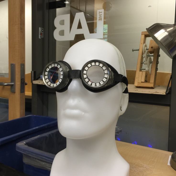
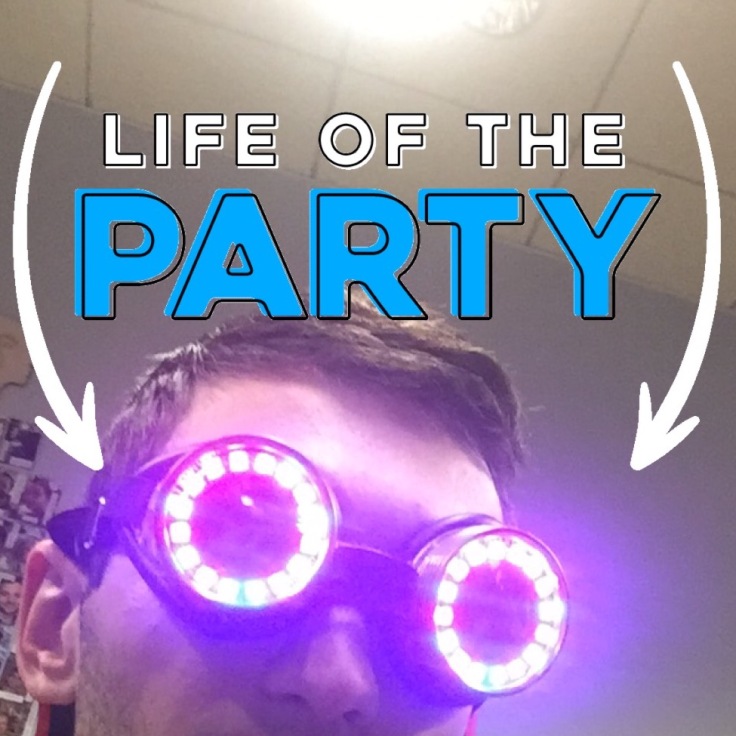
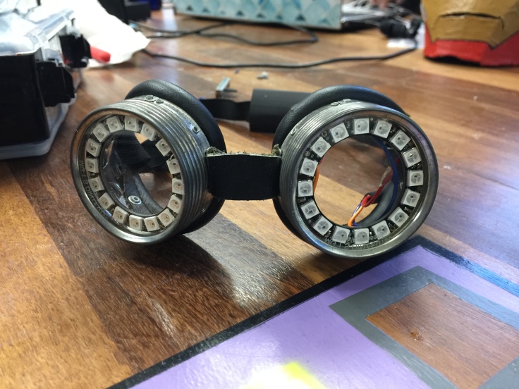
This project is designed to help jewelers and other workpeople see in tight places. They could also double as a set of cosplay goggles imitating your favorite musician. Controlled by bluetooth, the goggles have the ability to display many colors, including red for night and white for work.
MATERIALS:
PROCESS:
CHALLENGES:
RESOURCES:
CODE:
/*********************************************************************
CUSTOM REZZ GOGGLES, Michael Ettinger
Issues with anaimations…
Thanks to the CU BTU LAB for assistance, original code from Adafruit.
*********************************************************************/
#include <string.h>
#include <Arduino.h>
#include <SPI.h>
#if not defined (_VARIANT_ARDUINO_DUE_X_) && not defined (_VARIANT_ARDUINO_ZERO_)
#include <SoftwareSerial.h>
#endif
#include “Adafruit_BLE.h”
#include “Adafruit_BluefruitLE_SPI.h”
#include “Adafruit_BluefruitLE_UART.h”
#include “BluefruitConfig.h”
#include <Adafruit_NeoPixel.h>
/*=========================================================================
APPLICATION SETTINGS
FACTORYRESET_ENABLE Perform a factory reset when running this sketch
Enabling this will put your Bluefruit LE module
in a ‘known good’ state and clear any config
data set in previous sketches or projects, so
running this at least once is a good idea.
PIN Which pin on the Arduino is connected to the NeoPixels?
NUMPIXELS How many NeoPixels are attached to the Arduino?
———————————————————————–*/
#define FACTORYRESET_ENABLE 1
#define PIN 6
#define NUMPIXELS 32
/*=========================================================================*/
Adafruit_NeoPixel pixel = Adafruit_NeoPixel(NUMPIXELS, 6); // NeoPixel Object for Visor Strips
// Create the bluefruit object, either software serial…uncomment these lines
/*
SoftwareSerial bluefruitSS = SoftwareSerial(BLUEFRUIT_SWUART_TXD_PIN, BLUEFRUIT_SWUART_RXD_PIN);
Adafruit_BluefruitLE_UART ble(bluefruitSS, BLUEFRUIT_UART_MODE_PIN,
BLUEFRUIT_UART_CTS_PIN, BLUEFRUIT_UART_RTS_PIN);
*/
/* …or hardware serial, which does not need the RTS/CTS pins. Uncomment this line */
// Adafruit_BluefruitLE_UART ble(BLUEFRUIT_HWSERIAL_NAME, BLUEFRUIT_UART_MODE_PIN);
/* …hardware SPI, using SCK/MOSI/MISO hardware SPI pins and then user selected CS/IRQ/RST */
Adafruit_BluefruitLE_SPI ble(BLUEFRUIT_SPI_CS, BLUEFRUIT_SPI_IRQ, BLUEFRUIT_SPI_RST);
/* …software SPI, using SCK/MOSI/MISO user-defined SPI pins and then user selected CS/IRQ/RST */
//Adafruit_BluefruitLE_SPI ble(BLUEFRUIT_SPI_SCK, BLUEFRUIT_SPI_MISO,
// BLUEFRUIT_SPI_MOSI, BLUEFRUIT_SPI_CS,
// BLUEFRUIT_SPI_IRQ, BLUEFRUIT_SPI_RST);
// A small helper
void error(const __FlashStringHelper*err) {
Serial.println(err);
while (1);
}
// function prototypes over in packetparser.cpp
uint8_t readPacket(Adafruit_BLE *ble, uint16_t timeout);
float parsefloat(uint8_t *buffer);
void printHex(const uint8_t * data, const uint32_t numBytes);
// the packet buffer
extern uint8_t packetbuffer[];
/**************************************************************************/
/*!
@brief Sets up the HW an the BLE module (this function is called
automatically on startup)
*/
/**************************************************************************/
//additional variables
//Color
uint8_t red = 255;
uint8_t green = 255;
uint8_t blue = 255;
uint8_t animationState = 1;
int pos = 0, dir = 1; // Position, direction of “eye” for larson scanner animation
void setup(void)
{
//while (!Serial); // required for Flora & Micro
delay(500);
// turn off neopixel
pixel.begin(); // This initializes the NeoPixel library.
for(uint8_t i=0; i<NUMPIXELS; i++) {
pixel.setPixelColor(i, pixel.Color(0,0,0)); // off
}
colorWipe(pixel.Color(255, 255, 255), 15);
colorWipe(pixel.Color(0, 0, 0), 15);
pixel.show();
Serial.begin(115200);
Serial.println(F(“Adafruit Bluefruit Neopixel Color Picker Example”));
Serial.println(F(“————————————————“));
/* Initialise the module */
Serial.print(F(“Initialising the Bluefruit LE module: “));
if ( !ble.begin(VERBOSE_MODE) )
{
error(F(“Couldn’t find Bluefruit, make sure it’s in CoMmanD mode & check wiring?”));
}
Serial.println( F(“OK!”) );
if ( FACTORYRESET_ENABLE )
{
/* Perform a factory reset to make sure everything is in a known state */
Serial.println(F(“Performing a factory reset: “));
if ( ! ble.factoryReset() ){
error(F(“Couldn’t factory reset”));
}
}
/* Disable command echo from Bluefruit */
ble.echo(false);
Serial.println(“Requesting Bluefruit info:”);
/* Print Bluefruit information */
ble.info();
Serial.println(F(“Please use Adafruit Bluefruit LE app to connect in Controller mode”));
Serial.println(F(“Then activate/use the sensors, color picker, game controller, etc!”));
Serial.println();
ble.verbose(false); // debug info is a little annoying after this point!
/* Wait for connection */
while (! ble.isConnected()) {
delay(500);
}
Serial.println(F(“***********************”));
// Set Bluefruit to DATA mode
Serial.println( F(“Switching to DATA mode!”) );
ble.setMode(BLUEFRUIT_MODE_DATA);
Serial.println(F(“***********************”));
}
/**************************************************************************/
/*!
@brief Constantly poll for new command or response data
*/
/**************************************************************************/
void loop(void) {
/* Wait for new data to arrive */
uint8_t len = readPacket(&ble, BLE_READPACKET_TIMEOUT);
if (len == 0) return;
/* Got a packet! */
// printHex(packetbuffer, len);
// Color
if (packetbuffer[1] == ‘C’) {
uint8_t red = packetbuffer[2];
uint8_t green = packetbuffer[3];
uint8_t blue = packetbuffer[4];
Serial.print (“RGB #”);
if (red < 0x10) Serial.print(“0”);
Serial.print(red, HEX);
if (green < 0x10) Serial.print(“0”);
Serial.print(green, HEX);
if (blue < 0x10) Serial.print(“0”);
Serial.println(blue, HEX);
for(uint8_t i=0; i<NUMPIXELS; i++) {
pixel.setPixelColor(i, pixel.Color(red,green,blue));
}
pixel.show(); // This sends the updated pixel color to the hardware.
}
// Buttons
if (packetbuffer[1] == ‘B’) {
uint8_t buttnum = packetbuffer[2] – ‘0’;
boolean pressed = packetbuffer[3] – ‘0’;
Serial.print (“Button “); Serial.print(buttnum);
animationState = buttnum;
if (pressed) {
Serial.println(” pressed”);
} else {
Serial.println(” released”);
}
if (animationState == 1){
rainbow(20);
pixel.show(); // This sends the updated pixel color to the hardware.
}
if (animationState == 2){
colorWipe(pixel.Color(114, 0, 255), 20);
colorWipe(pixel.Color(0, 0, 0), 20);
colorWipe(pixel.Color(0, 50, 255), 20);
colorWipe(pixel.Color(0, 0, 0), 20);
colorWipe(pixel.Color(0, 220, 255), 20);
colorWipe(pixel.Color(0, 0, 0), 20);
colorWipe(pixel.Color(255, 225, 255), 20);
colorWipe(pixel.Color(0, 0, 0), 20);
pixel.show(); // This sends the updated pixel color to the hardware.
}
if (animationState == 3){
for(uint16_t i=0; i<pixel.numPixels(); i++) {
pixel.setPixelColor(i, pixel.Color(0,0,0));
}
pixel.setBrightness(255);
colorWipe(pixel.Color(0, 0, 255), 20);
colorWipe(pixel.Color(0, 0, 0), 20);
pixel.show(); // This sends the updated pixel color to the hardware.
}
if (animationState == 4){
for(uint16_t i=0; i<pixel.numPixels(); i++) {
pixel.setPixelColor(i, pixel.Color(0,0,0));
}
pixel.setBrightness(255);
rainbowCycle(10);
pixel.show(); // This sends the updated pixel color to the hardware.
}
}
}
// Fill the dots one after the other with a color
void colorWipe(uint32_t c, uint8_t wait) {
for(uint16_t i=0; i<pixel.numPixels(); i++) {
pixel.setPixelColor(i, c);
pixel.show();
delay(wait);
}
}
void larsonScanner(uint32_t c, uint8_t wait){
int j;
for(uint16_t i=0; i<pixel.numPixels()+5; i++) {
// Draw 5 pixels centered on pos. setPixelColor() will clip any
// pixels off the ends of the strip, we don’t need to watch for that.
pixel.setPixelColor(pos – 2, 0x003b85); // Dark red
pixel.setPixelColor(pos – 1, 0x005ed2); // Medium red
pixel.setPixelColor(pos , 0x00c0ff); // Center pixel is brightest
pixel.setPixelColor(pos + 1, 0x005ed2); // Medium red
pixel.setPixelColor(pos + 2, 0x003b85); // Dark red
pixel.show();
delay(wait);
// Rather than being sneaky and erasing just the tail pixel,
// it’s easier to erase it all and draw a new one next time.
for(j=-2; j<= 2; j++) pixel.setPixelColor(pos+j, 0);
// Bounce off ends of strip
pos += dir;
if(pos < 0) {
pos = 1;
dir = -dir;
} else if(pos >= pixel.numPixels()) {
pos = pixel.numPixels() – 2;
dir = -dir;
}
}
//colorWipe(pixel.Color(0, 0, 0), 20);
}
void flashRandom(int wait, uint8_t howmany) {
for(uint16_t i=0; i<howmany; i++) {
// get a random pixel from the list
int j = random(pixel.numPixels());
// now we will ‘fade’ it in 5 steps
for (int x=0; x < 5; x++) {
int r = red * (x+1); r /= 5;
int g = green * (x+1); g /= 5;
int b = blue * (x+1); b /= 5;
pixel.setPixelColor(j, pixel.Color(r, g, b));
pixel.show();
delay(wait);
}
// & fade out in 5 steps
for (int x=5; x >= 0; x–) {
int r = red * x; r /= 5;
int g = green * x; g /= 5;
int b = blue * x; b /= 5;
pixel.setPixelColor(j, pixel.Color(r, g, b));
pixel.show();
delay(wait);
}
}
// LEDs will be off when done (they are faded to 0)
}
void rainbow(uint8_t wait) {
uint16_t i, j;
for(j=0; j<256; j++) {
for(i=0; i<pixel.numPixels(); i++) {
pixel.setPixelColor(i, Wheel((i+j) & 255));
}
pixel.show();
delay(wait);
}
}
// Slightly different, this makes the rainbow equally distributed throughout
void rainbowCycle(uint8_t wait) {
uint16_t i, j;
for(j=0; j<256*5; j++) { // 5 cycles of all colors on wheel
for(i=0; i< pixel.numPixels(); i++) {
pixel.setPixelColor(i, Wheel(((i * 256 / pixel.numPixels()) + j) & 255));
}
pixel.show();
delay(wait);
}
}
//Theatre-style crawling lights.
void theaterChase(uint32_t c, uint8_t wait) {
for (int j=0; j<10; j++) { //do 10 cycles of chasing
for (int q=0; q < 3; q++) {
for (int i=0; i < pixel.numPixels(); i=i+3) {
pixel.setPixelColor(i+q, c); //turn every third pixel on
}
pixel.show();
delay(wait);
for (int i=0; i < pixel.numPixels(); i=i+3) {
pixel.setPixelColor(i+q, 0); //turn every third pixel off
}
}
}
}
//Theatre-style crawling lights with rainbow effect
void theaterChaseRainbow(uint8_t wait) {
for (int j=0; j < 256; j++) { // cycle all 256 colors in the wheel
for (int q=0; q < 3; q++) {
for (int i=0; i < pixel.numPixels(); i=i+3) {
pixel.setPixelColor(i+q, Wheel( (i+j) % 255)); //turn every third pixel on
}
pixel.show();
delay(wait);
for (int i=0; i < pixel.numPixels(); i=i+3) {
pixel.setPixelColor(i+q, 0); //turn every third pixel off
}
}
}
}
// Input a value 0 to 255 to get a color value.
// The colours are a transition r – g – b – back to r.
uint32_t Wheel(byte WheelPos) {
WheelPos = 255 – WheelPos;
if(WheelPos < 85) {
return pixel.Color(255 – WheelPos * 3, 0, WheelPos * 3);
}
if(WheelPos < 170) {
WheelPos -= 85;
return pixel.Color(0, WheelPos * 3, 255 – WheelPos * 3);
}
WheelPos -= 170;
return pixel.Color(WheelPos * 3, 255 – WheelPos * 3, 0);
}
 SUMMARY:
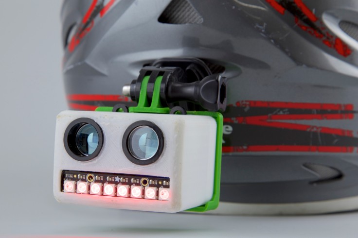
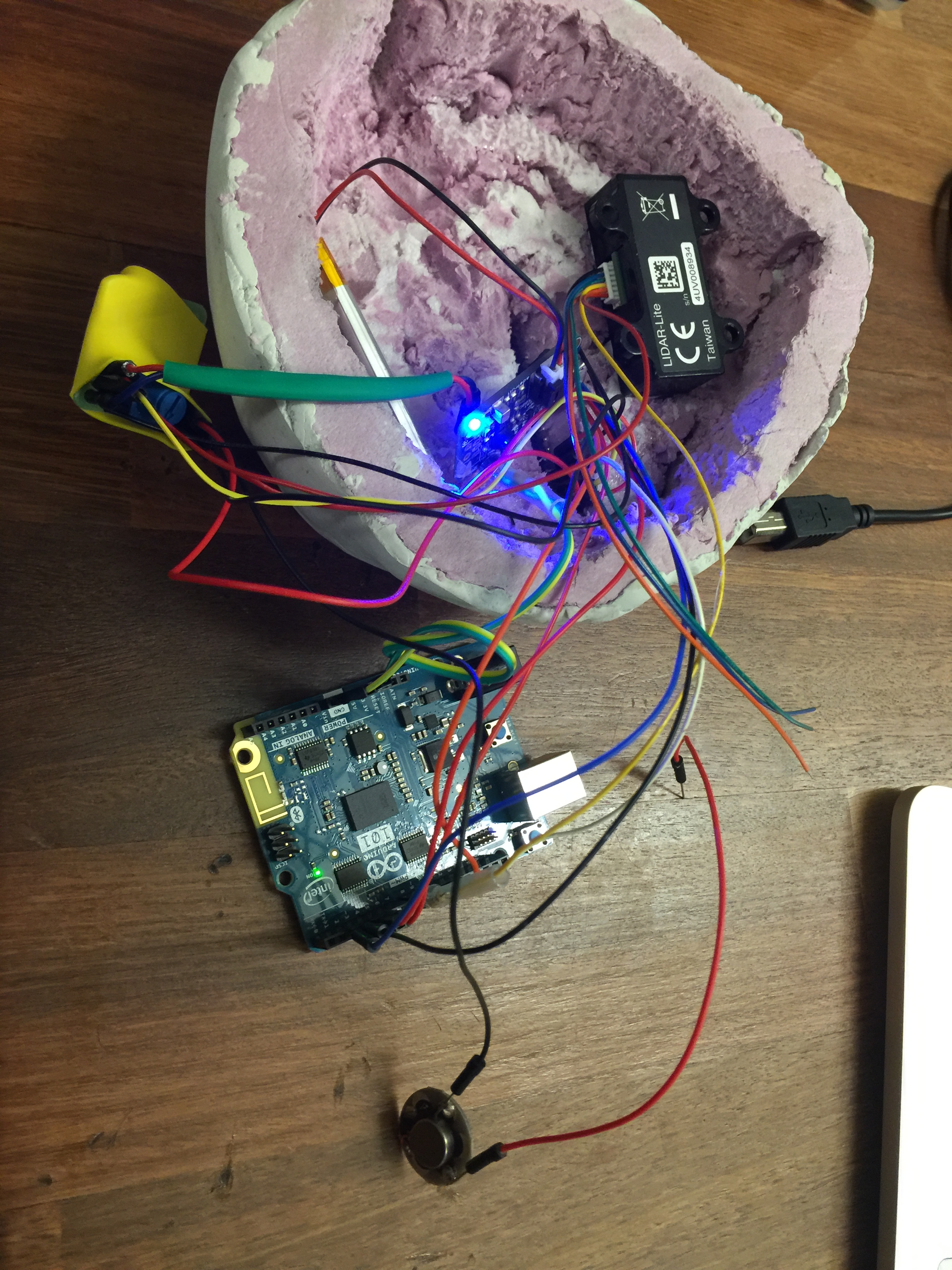
This continuing project solves the common occurrence of drivers becoming dangerously close to drivers of motorcycles and bicycles, potentially dragging them underneath their vehicle. The product is a rear helmet mounted piece which gives a tiny pulse to the wearer, and displays a message to the intruder of space by an LCD display when a LIDAR module senses the improper distance. It is designed to non verbally communicate with a driver to indicate you would appreciate some more space to move about your space in the lane. This will revolutionize how all drivers communicate with two wheeled vehicles, and will lead to safer roads.
MATERIALS:
PROCESS:
CHALLENGES:
RESOURCES:
CODE:
/*——————————————————————————
LIDARLite Arduino Library
GetDistancePwm
This example shows how to read distance from a LIDAR-Lite connected over the
PWM interface.
Connections:
LIDAR-Lite 5 Vdc (red) to Arduino 5v
LIDAR-Lite Ground (black) to Arduino GND
LIDAR-Lite Mode control (yellow) to Arduino digital input (pin 3)
LIDAR-Lite Mode control (yellow) to 1 kOhm resistor lead 1
1 kOhm resistor lead 2 to Arduino digital output (pin 2)
(Capacitor recommended to mitigate inrush current when device is enabled)
680uF capacitor (+) to Arduino 5v
680uF capacitor (-) to Arduino GND
See the Operation Manual for wiring diagrams and more information:
Click to access LIDAR_Lite_v3_Operation_Manual_and_Technical_Specifications.pdf
——————————————————————————*/
#include <Adafruit_NeoPixel.h>
#define PIN 3
#define N_LEDS 8
unsigned long pulseWidth;
volatile long cm;
Adafruit_NeoPixel strip = Adafruit_NeoPixel(N_LEDS, PIN, NEO_GRB + NEO_KHZ800);
void setup()
{
strip.begin();
{
Serial.begin(115200); // Start serial communications
pinMode(8, OUTPUT); // Set pin 8 as trigger pin
digitalWrite(8, LOW); // Set trigger LOW for continuous read
pinMode(9, INPUT); // Set pin 9 as monitor pin
}
}
void loop()
{
pulseWidth = pulseIn(9, HIGH); // Count how long the pulse is high in microseconds
// If we get a reading that isn’t zero, let’s print it
//if(pulseWidth != 0)
//{
//pulseWidth = pulseWidth / 10; // 10usec = 1 cm of distance
cm = microsecondstocm(pulseWidth);
Serial.println(cm); // Print the distance
if(cm <= 40)
{
//chase(strip.Color(225, 0, 0)); // no color
chase(strip.Color(255, 0, 0)); // Red
//delay(50);
}
//chase(strip.Color(255, 0, 0)); // Red
//}
}
long microsecondstocm(long microseconds)
{
return microseconds / 29 / 2;
}
static void chase(uint32_t c) {
for(uint16_t i=0; i<strip.numPixels()+4; i++) {
strip.setPixelColor(i , c); // Draw new pixel
strip.setPixelColor(i-4, 0); // Erase pixel a few steps back
strip.show();
delay(25);
}
}
SUMMARY:
This innovative product solves the common occurrence of drivers becoming dangerously close to drivers of motorcycles and bicycles, potentially dragging them underneath their vehicle. This product is a rear helmet mounted piece which gives a tiny pulse to the wearer, and displays a message to the intruder of space by an LCD display when a LIDAR module senses the improper distance. It is designed to non verbally communicate with a driver to indicate you would appreciate some more space to move about your space in the lane. This will revolutionize how all drivers communicate with two wheeled vehicles, and will lead to safer roads.
MATERIALS:
PROCESS:
CHALLENGES:
RESOURCES:
CODE:
/*
* The Rear View Monitor
* Designed by Michael Ettinger
* Assistance from The University of Colroado Boulder BTU Lab, Instructables
* Relies on libraries for LidarLite v3 from Garmin Inc.
*
*
* This wearable senses how far a car is behind a 2 wheeled vehicle and alerts the
* user if there is a danger, along with a visual aid for the rear driver.
*/
int const motor = 6;
#include
long pulseWidth;
long cm;
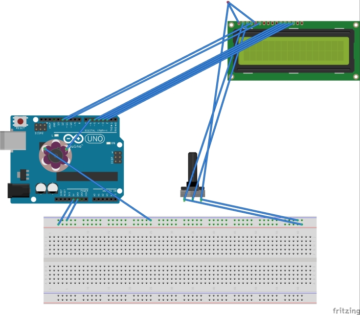
LiquidCrystal lcd(12, 11, 5, 4, 3, 2);
void setup()
{
Serial.begin(9600); // Start serial communications
pinMode(8, OUTPUT); // Set pin 2 as trigger pin
digitalWrite(8, LOW); // Set trigger LOW for continuous read
pinMode(9, INPUT); // Set pin 3 as monitor pin
//pinMode(6, OUTPUT);
}
void loop()
{
pulseWidth = pulseIn(9, HIGH); // Count how long the pulse is high in microseconds
cm = microsecondstocm(pulseWidth);
Serial.println(cm);
delay(100);
pinMode(motor,OUTPUT);
if(cm <= 20)
{
lcd.begin(8, 2); //is 16×1, adressed as 8×2
lcd.setCursor(0,1); //init right hand side
lcd.home(); //back to start
lcd.clear();
// Print a message to the LCD.
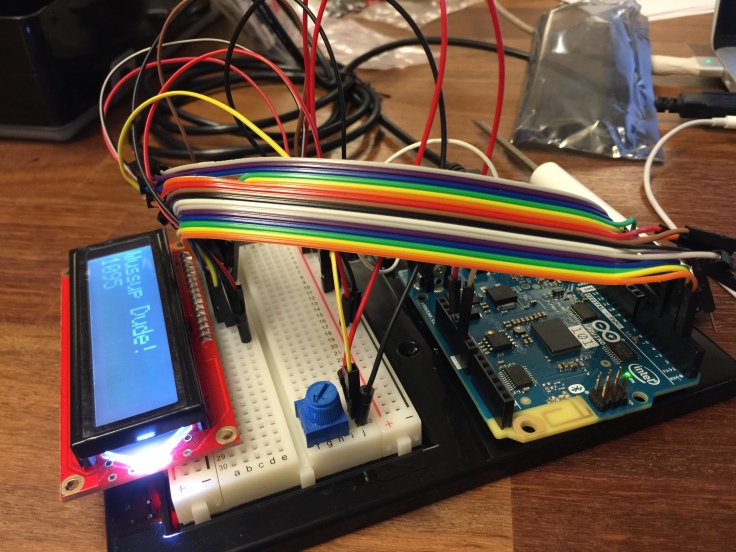
lcd.print(” Stay”); //print left side (6 Character MAX)
lcd.setCursor(0,1); //go to right
lcd.print(“Back!”); //print right side
digitalWrite(motor, HIGH);
delay(500);
digitalWrite(motor, LOW);
delay(500);
}
else{
lcd.clear();
}
// If we get a reading that isn’t zero, let’s print it
//if(cm != 0)
//{
//cm = cm / 10; // 10usec = 1 cm of distance
//Serial.println(cm); // Print the distance
//}
}
long microsecondstocm(long microseconds)
{
return microseconds / 29 / 2;
}
Materials: Safety Gear, Keys.
To start your motorcycle, you must first check that everything is in operating condition. First, check your front and back tires for proper wear. Ensure the tires are not at the wear bars. Check for proper tire inflation pressure, remember you only have 2 wheels keeping you on the road, make sure they are up to specifications.
Sit on the bike. Insert and turn your key until dashboard lights appear. Hold down the clutch. Move the gear with your left foot into neutral, a light will appear on the dashboard. Turn the engine cut-off switch to ON. Push the engine starter. You may now safely dismount the bike and ensure that all headlights and tail lights are working. Your ready to ride!


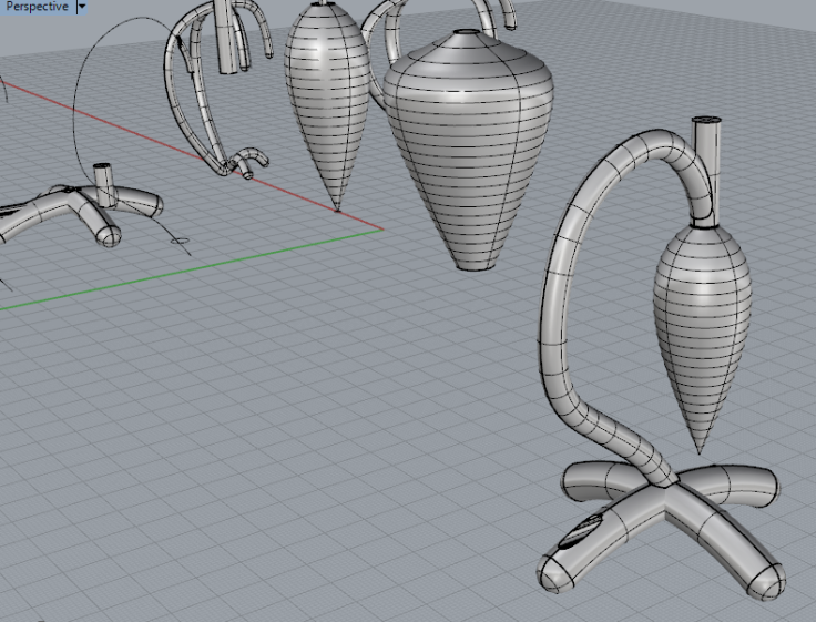
Returning to the digitally fabricated lamp, this project builds on the failures and success of the last project to create a second iteration of the digitally fabricated lamp. This second attempt breaks up the base into multiple pieces to be assembled later, in order to allow for easier wiring routing access. The bulky base has now been changed into a slim shape similar to the addition symbol, and incorporates a two part hanger in the middle that will be plasti-welded together for the final form to allow for easy routing of 4 individual wires. The shade will be laser cut from acrylic pieces and welded together as well to form the final glowing stinger.


Partner – https://paigelalleman.wordpress.com/category/form/
We began wanting to remake the pinch connectors in backpack straps, but after deciding whats here is already adequate, we moved to digitally forming a lamp. This lamp was originally modeled after the intricate workings of a shell, however when preliminary prints failed, we moved to a more solid and geometric structure which would be better to print. The print was assisted through small changes such as chamfered edges instead of 90º turns which the printer handled well to create smooth turns. The 2 pieces are welded together however minor design errors made the internal routing of cables impossible, the solution would be to create 3 pieces for the single cable turn, then weld them together.


For this project, I explored the existing topographic data from state geologic surveys in the areas I considered home. I drew out the different elevations, extruded and capped them, and manually moved them into the proper elevations.


For my multiples project, I decided to duplicate my key chain which has the keys to everything I use on a daily basis. Keys are all unique in how they are shaped, rounded, and sized but still each unique, which is why I finally decided on the concept. Each key was drawn out individually, extruded, and boolean’d to recreate each shape on the ring. This was finally brought together with a ring holding them together as they would be in real life.


