 SUMMARY:
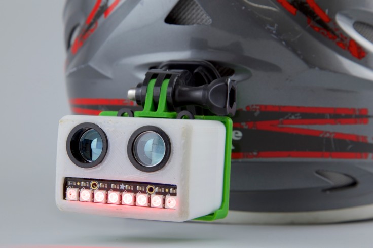
This continuing project solves the common occurrence of drivers becoming dangerously close to drivers of motorcycles and bicycles, potentially dragging them underneath their vehicle. The product is a rear helmet mounted piece which gives a tiny pulse to the wearer, and displays a message to the intruder of space by an LCD display when a LIDAR module senses the improper distance. It is designed to non verbally communicate with a driver to indicate you would appreciate some more space to move about your space in the lane. This will revolutionize how all drivers communicate with two wheeled vehicles, and will lead to safer roads.
MATERIALS:
- Qduino Mini (https://www.sparkfun.com/products/13614)
- eTextiles Battery 110 mAh 2C (https://www.sparkfun.com/products/13112)
- LidarLite V3 (https://www.sparkfun.com/products/14032)
- GoPro Helmet Mount
- Snapable ProtoBoard
- Heat Shrink Tubing
- HIPS 3D Printing Filament
PROCESS:
- Re-visit project 1
- Re-Order new parts thinking about the space issues seen in project 1.
- Test parts prior to deciding final use.
- Design new case
- Using Rhino, I designed a case to fit onto a generic gopro mount.
- Print Case. This version did not look good or have enough space for electronics.
- Re-Design case with smoother look
- Print case. This version printed okay, but a HIPS tab broke apart, requiring a reprint.
- Re-Design Case. This version looked good but needed more space for the basic electronics.
- Print case. This model is the final for this project.
- Wire circuit using similar pinout to project 1
- Re-Code using code from project 1.
- Debug
- Install on helmet
- Success!
CHALLENGES:
- The case still needs tweaking, still large and bulky
- A power button is essential to the project. The Arduino board with power supply needs to be placed in a more accessible spot exiting the case
RESOURCES:
- http://static.garmin.com/pumac/LIDAR_Lite_v3_Operation_Manual_and_Technical_Specifications.pdf
- https://learn.adafruit.com/adafruit-neopixel-uberguide
- https://learn.adafruit.com/neopixel-painter/test-neopixel-strip
CODE:
/*——————————————————————————
LIDARLite Arduino Library
GetDistancePwm
This example shows how to read distance from a LIDAR-Lite connected over the
PWM interface.
Connections:
LIDAR-Lite 5 Vdc (red) to Arduino 5v
LIDAR-Lite Ground (black) to Arduino GND
LIDAR-Lite Mode control (yellow) to Arduino digital input (pin 3)
LIDAR-Lite Mode control (yellow) to 1 kOhm resistor lead 1
1 kOhm resistor lead 2 to Arduino digital output (pin 2)
(Capacitor recommended to mitigate inrush current when device is enabled)
680uF capacitor (+) to Arduino 5v
680uF capacitor (-) to Arduino GND
See the Operation Manual for wiring diagrams and more information:
Click to access LIDAR_Lite_v3_Operation_Manual_and_Technical_Specifications.pdf
——————————————————————————*/
#include <Adafruit_NeoPixel.h>
#define PIN 3
#define N_LEDS 8
unsigned long pulseWidth;
volatile long cm;
Adafruit_NeoPixel strip = Adafruit_NeoPixel(N_LEDS, PIN, NEO_GRB + NEO_KHZ800);
void setup()
{
strip.begin();
{
Serial.begin(115200); // Start serial communications
pinMode(8, OUTPUT); // Set pin 8 as trigger pin
digitalWrite(8, LOW); // Set trigger LOW for continuous read
pinMode(9, INPUT); // Set pin 9 as monitor pin
}
}
void loop()
{
pulseWidth = pulseIn(9, HIGH); // Count how long the pulse is high in microseconds
// If we get a reading that isn’t zero, let’s print it
//if(pulseWidth != 0)
//{
//pulseWidth = pulseWidth / 10; // 10usec = 1 cm of distance
cm = microsecondstocm(pulseWidth);
Serial.println(cm); // Print the distance
if(cm <= 40)
{
//chase(strip.Color(225, 0, 0)); // no color
chase(strip.Color(255, 0, 0)); // Red
//delay(50);
}
//chase(strip.Color(255, 0, 0)); // Red
//}
}
long microsecondstocm(long microseconds)
{
return microseconds / 29 / 2;
}
static void chase(uint32_t c) {
for(uint16_t i=0; i<strip.numPixels()+4; i++) {
strip.setPixelColor(i , c); // Draw new pixel
strip.setPixelColor(i-4, 0); // Erase pixel a few steps back
strip.show();
delay(25);
}
}

Leave a comment